상담완료 | Star Baum님의 문의
페이지 정보
작성자 Star Baum 작성일24-06-28 07:34 조회8회 댓글0건관련링크
본문
이메일 : star_baum@googlemail.com 연락처 : 예식일 : Warning: These 9 Mistakes Will Destroy Your Rs485 Cable 문의내용:
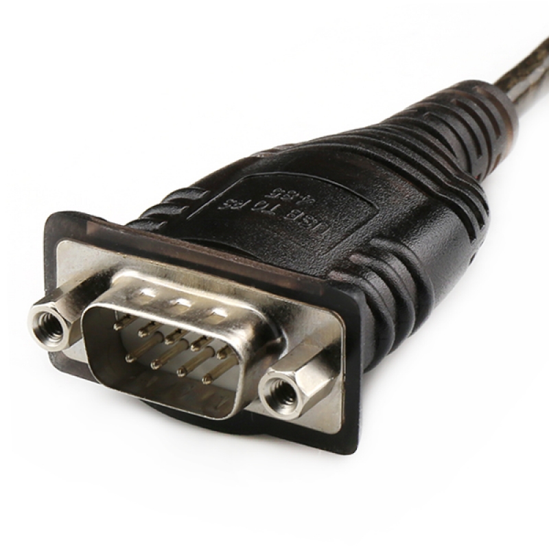
Rs485 cable is essentially a signal cable with a twisted pair structure, additionally shielded with 2 layers of noise protection used in industrial communication. Otherwise a full 6 wire cable must be used. 3106A is what I typically use to wire balanced audio. In contrast to RS-422, which has a driver circuit which cannot be switched off, RS-485 drivers use three-state logic allowing individual transmitters to be deactivated. This allows RS-485 to implement linear bus topologies using only two wires. Ideally, the two ends of the cable will have a termination resistor connected across the two wires. Each sensor has two mounting holes for attaching it to walls and other surfaces. There are three flag bits implemented in the SPSR (SPI status register). Then reading the data that was received (by reading the SPDR) or initiating a new data transfer (by writing to the SPDR) automatically clears the SPIF flag.
After a data transfer is initiated by writing to the SPDR data register, the processor may poll the SPSR status register until the SPIF flag is set. Alternatively, the if the SPI interrupts are enabled, the SPI interrupt handler determines what caused the interrupt by reading the SPSR register to see which of the three status bits is set. The only possible reference is the reading of the displayed value, for example, of the current. All gaming operator will be brought to you hoping to add, tailored for the heater, as well as pre-programmed by the use of asked parameter typical valuations, alongside warmth figure out time, heater warm process, RS485 home correct not to mention selection current and also number. These devices allow you to view and modify the parameters of heat controllers, connected to the RS485 port via the communication protocol and the NCP to monitor the parameters of heat meters (Mbus), connected to RS232 port via a converter RS232/Mbus (M-bus master). Although the devices would share the same network, communications would only be understandable by members of the same group. The symmetrical pin layout of the RJ11 sockets on the Unitronics PLCs allows an easy way of interconnecting the PLCs with both RS232 and RS485 communications.

The diagram below shows a basic RS485 cable for use with the RJ11 socket on Unitronics PLCs. If handshaking is not necessary, an ordinary 4 wire telephone cable could be used, provided that the pins are cross-connected as shown in the picture below. Twisted pair structure: Rs485 anti-interference cable has a twisted pair conductor structure. Industrial automation systems: In the industrial automation sector, rs485 signal cables play a vital role in connecting and remotely controlling motors. Stable connections play a crucial role in managing and controlling access to secure areas, optimizing system performance. The SPE bit turns on the SPI system. It is important to note that when the CPHA bit is 0, the /SS line must be de-asserted and re-asserted between each successive data byte exchange (68HC11 Reference Manual, Section 8.3.2). If the CPHA bit is 1, the /SS line may be tied low between successive transfers. The flexibility and power of the 68HC11’s serial peripheral interface supports high speed communication between the 68HC11 and other synchronous serial devices. RS-485, also known as TIA-485(-A) or EIA-485, is a standard, originally introduced in 1983, defining the electrical characteristics of drivers and receivers for use in serial communications systems. In general, all devices on a network should use the same phase, polarity, and baud rate clock signal.
Pre-coded device drivers configure the SPI for a standard data format, and it is easy to customize a data format and baud rate for your application. The foreword to the standard references The Telecommunications Systems Bulletin TSB-89 which contains application guidelines, including data signaling rate vs. One of the key advantages also is that RS-485 can drive data a long distance. It will indicate when each one starts and ends. Note that the data is changed by the transmitting device one half clock cycle before it is valid. The clock’s polarity is controlled by a bit named CPOL (clock polarity) and its phase is controlled by CPHA (clock phase). This bit should be set only after all other SPI configuration is complete. Consult the data sheets for any peripheral devices that you are interfacing to the SPI and, if a different configuration is needed, follow the instructions below to set up the appropriate SPI data transfer protocol. Alarm systems: Rs485 cables in alarm systems help transfer alarm signals and information from alarm devices to the control center. Users can browse through the alarm list or acknowledge alarms easily via function keys on the vertical bar.
댓글목록
등록된 댓글이 없습니다.

