상담신청 | Mindy님의 문의
페이지 정보
작성자 Mindy 작성일24-06-05 09:40 조회25회 댓글0건관련링크
본문
이메일 : mindygrayndler@verizon.net 연락처 : 예식일 : Do You Make These Simple Mistakes In Rs485 Cable? 문의내용:
Grounds between buildings may vary by a small voltage, but with very low impedance and hence the possibility of catastrophic currents - enough to melt signal cables, PCB traces, and transceiver devices. Because a mark (logic 1) condition is traditionally represented (e.g. in RS-232) with a negative voltage and space (logic 0) represented with a positive one, A may be considered the non-inverting signal and B as inverting. If A is negative with respect to B, the state is binary 1. The reversed polarity (A positive with respect to B) is binary 0. The standard does not assign any logic function to the two states. The foreword to the standard references The Telecommunications Systems Bulletin TSB-89 which contains application guidelines, including data signaling rate vs. The standard is jointly published by the Telecommunications Industry Association and Electronic Industries Alliance (TIA/EIA). 00-3) or standard 12V power supplies. To get the solar PV power from the roof down to the basement shed, we purchased 20 meters of 6mm armoured cable; this was routed down the back of the house and into the shed through the stone wall.
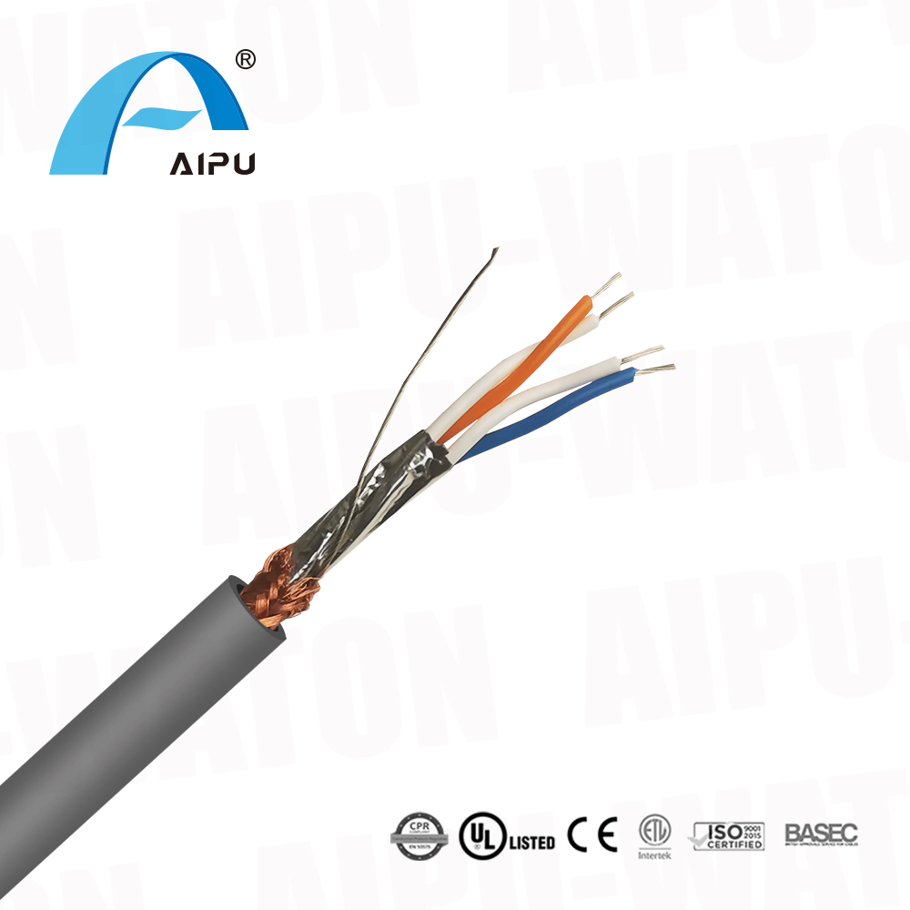
The main difference is, that pin 1 and 6 on the RJ11 socket of the MJ20-PRG module are used as power supply. These pins are normally used for the DTR, data terminal ready and DSR, data set ready signals. When in full RS232 mode, the six available pins are assigned to the most used RS232 signals. The RS485 system used for Modbus communication provides a main cable (Bus or backbone), to which all the devices have to be connected with branches (also known as stubs) that are as short as possible. RS-422 and RS-485 Standards Overview and System Configurations, Application Report (pdf). It does not specify or recommend any communications protocol; Other standards define the protocols for communication over an RS-485 link. RS-485 does not define a communication protocol; merely an electrical interface. RS485 interface gives some more benefits compared to RS232: simplicity and the robustness for long distance transfer. What communication protocols are supported by RS485? Normally pin 7 (RTS) and pin 4 (DTR) are used on the DB9 connector. You can easily connect more devices by splitting the cable at one connector and adding another cable to it. The RJ11 socket is interesting, because the manufacturer choose to have a symmetrical pin-layout, just as with the MMJ connector on DECconnect systems and the RJ45 jack in the Yost standard.
The diagram below shows a basic RS485 cable for use with the RJ11 socket on Unitronics PLCs. This MJ20-PRG module clicks in the PLC and provides one RJ11 socket for serial communications with a PC. On some PLC models it is possible to mix RS232 and RS485 communications. For RS232 a crossover cable is used where pin 1 is connected with pin 6 at the other connector, pin 2 with pin 5, etc. This interconnects the transmit and receive signals of both PLCs, and also the handshaking signals DTR and DSR. If we want to connect a PC with an Unitronics PLC, for example for programming or debugging reasons, we need a connection cable which is on one side fitted with a female DB9 connector, and on the other side with an RJ11 jack. To prevent noise to interfere with the communications, often twisted pair cable is used. For communications, many of their products are equipped with an RS232 or RS485 serial port.
Bus Probes are very compact (measuring only 40x36mm externally) and sport an attractive look and feel. We installed a new Micro SD card with the latest Raspberry Pi OS, and after updating the software, the serial port and i2c bus were enabled. This module is powered by the RS232 port from the connecting computer. The circuit uses optical isolation (opto-coupler) to isolate your RS232 port from the RS485 cables. Using the Solis Data Logging Stick, which uses WiFi to communicate, we were able to set up the inverter to send data to the remote soliscloud service, but we could not find any way to get capture data apart from scraping the basic status page built into the WiFi adapter which only gave watts being produced and daily output. After several frustrating days of trying different combinations of RS485 hats, different wiring connections, with and without termination resistors and ordering a USB RS485 adapter which would also fail to connect, we tried to install the Data logging WiFi adapter. If multiple analog input meters or transmitters are digitally addressed in command mode on an RS485 line using the Modbus RTU protocol or the Custom ASCII protocol, the rate becomes about 2 readings per second.
댓글목록
등록된 댓글이 없습니다.
